Adaptive Grind Force Control™ reduces cycle time by setting the desired normal grinding force rather than the infeed velocity. This results in faster metal removal rates, limited only by available power.
Real Time Deflection Compensation
Real Time Deflection Compensation™ eliminates dwell time by compensating in real time for machine deflections that result in size and taper variations.
True Normal
True Normal™ eliminates diamond roll form dressers for contour dressing. We can grind any profile into the wheel using a single point or rotary diamond disk
We have demonstrated that our EPS system with Maximizer software can do 3 things that no one else in the industry can do:
Dress any contour without additional tooling with our True Normal™ Contour Dressing software
Maximize metal removal rates with Adaptive Grind Force Control™
Maintain print tolerances at higher metal removal rates with Real Time Deflection Compensation™
We now are offering complete machines in either SingleTool or MultiTool format. If you wish to incorporate EPS into your platform or retrofit existing machines, we offer EPS Hardware with EPS Maximizer™ software and Siemens Sinumerik CNC control and drives. Please contact us if you’d like to learn more or to arrange a demonstration.
True Normal
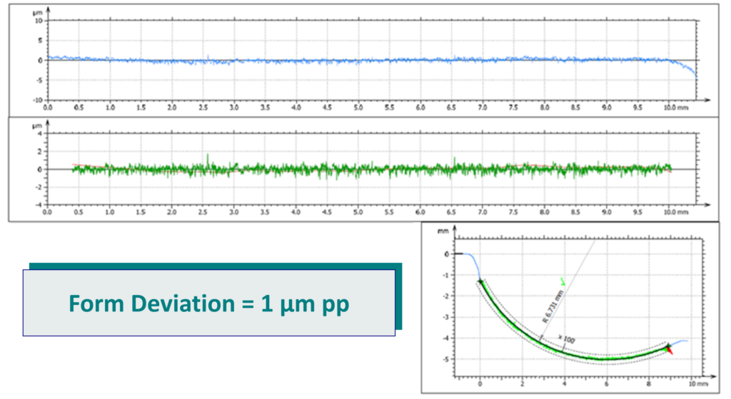
Using our “A” axis, True Normal contour dressing keeps the grinding wheel perpendicular to the diamond during contour dress operations. This enables us to generate accurate contour dress profiles. The adjacent figure shows 1.0 μm pp form deviation obtained grinding a 6.73 mm radius.
Adaptive Grind Force Control
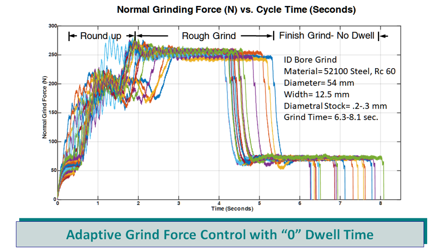
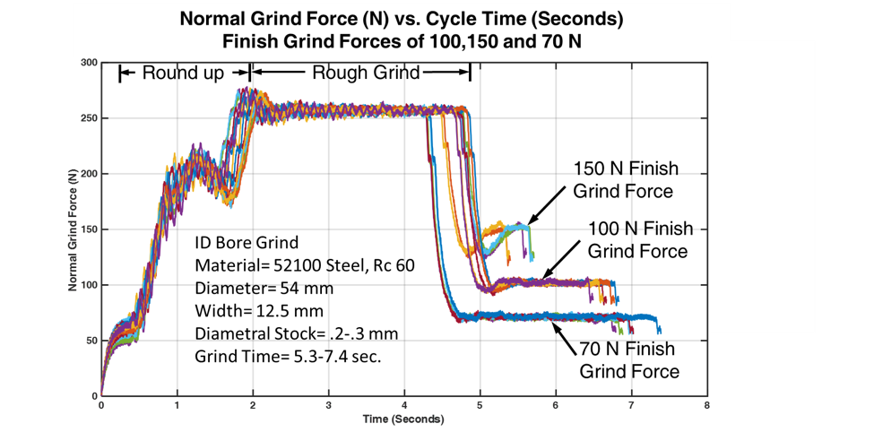
The figure to the left shows the control of the normal grinding force achieved by the machine with EPS Maximizer during an ID grind. These curves show round up, rough and finish grind forces for 20 grind cycles versus cycle time. The workpiece was a 54 mm ID x 12.4 mm wide 52100 steel bearing ring. The grind cycle begins with a gap eliminator phase, followed by a workpiece round up phase and a 250 N rough grind phase. The grind force then rapidly, changes to the finish grind force of 70 N. Notice that there are no dwells in any portion of the grind cycle.
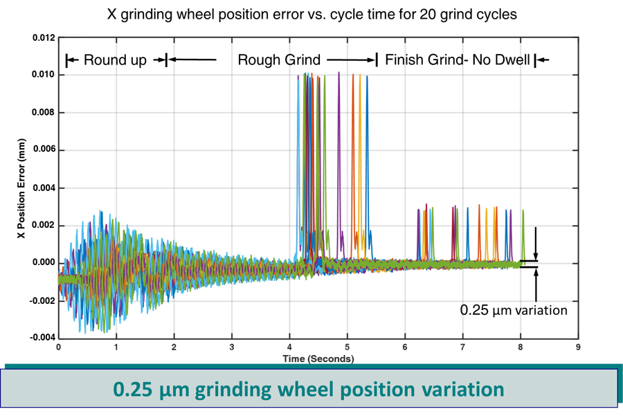
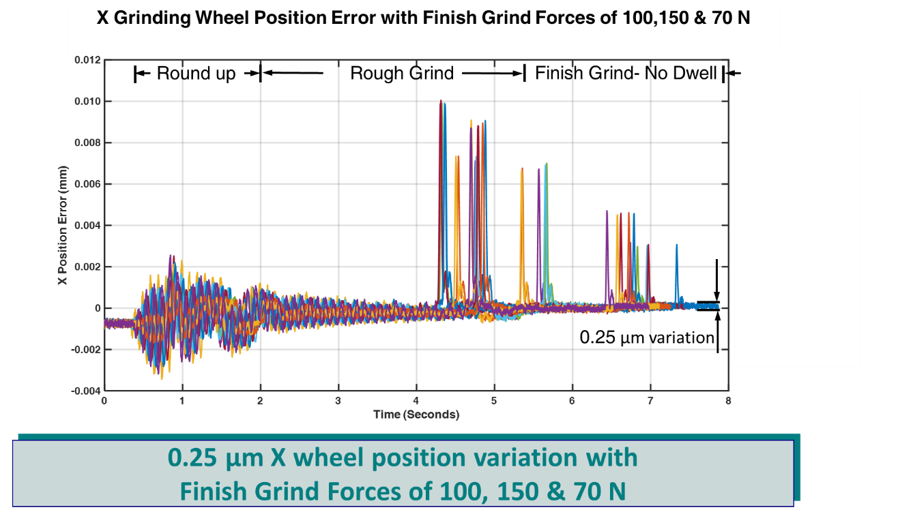
Our system can capture the real time position error of the grinding wheel during the grinding cycle. The figure to the right shows the X direction (infeed direction) position error versus cycle time for the 20 grind cycles shown on the previous grind force versus cycle time figure. These errors include those resulting from the positioning system, grind forces and vibration. As expected, the largest error occurs during the round up portion of the cycle when the workpiece is out of round. This error is about +/- 3 microns. During rough grind, the error the decreases to +/- 0.5 µm and during finish grind the error is further reduced to +/- 0.125µm . The first group of “spikes” occur during the quick transition from the rough grind force to the finish grind force. The last group of “spikes” occurs when the wheel is retracted from the part at the end of the grind cycle.
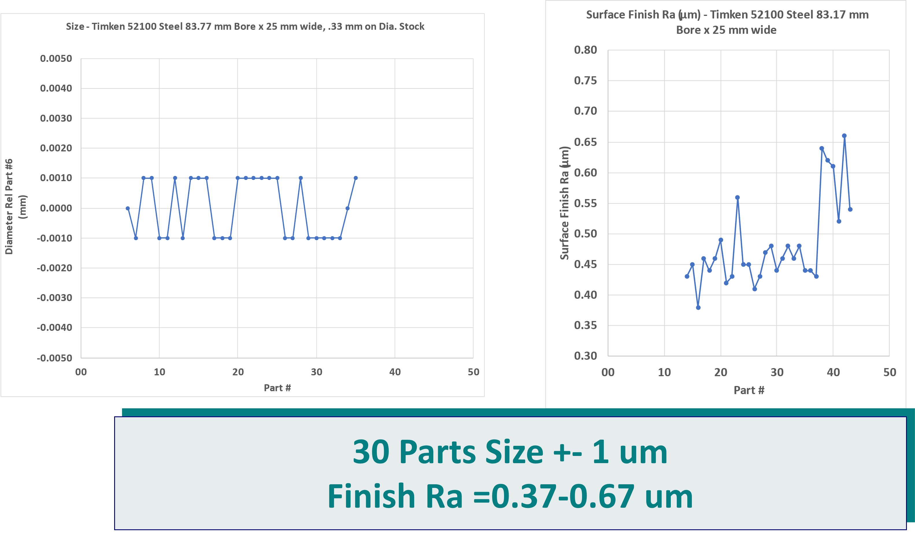
The figure to the left shows the diametral variation of the 83 mm bores ground with EPS Maximizer Adaptive Grind Force Control™ and Real Time Deflection Compensation™ for a 30 part run was +- 1.0 µm. The total grind time was 11 sec and 0.33 mm of stock was removed.
Real Time Deflection Compensation
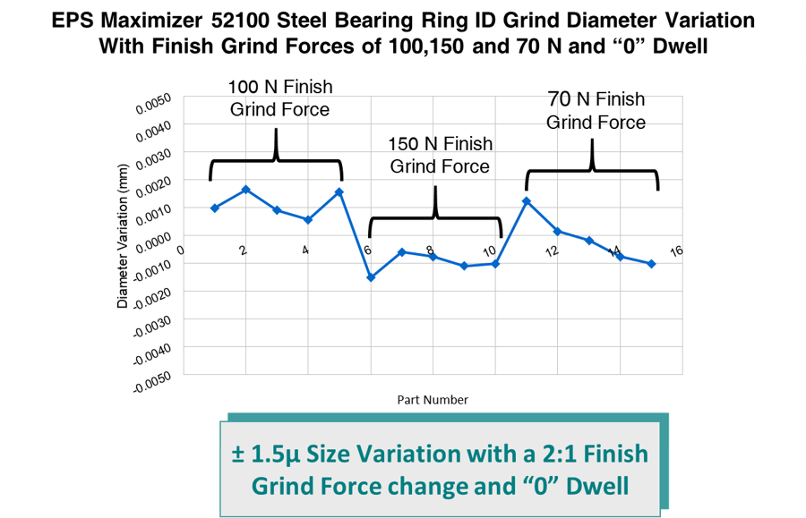
To demonstrate the effectiveness of our EPS Maximizer Real Time Deflection Compensation™ we ground 15 workpieces with a 250 N rough grind force and varied only the finish grind force. Real Time Deflection Compensation compensated for the quill, spindle and machine deflections. Again, there was no dwell in any portion of the grind cycle. We first ground 5 parts at 100 N finish grind force, then 5 at 150 N and finished up by grinding 5 more at a 70 N finish grind force as shown on the figure to the left.
The figure to the right shows the grinding wheel X position error versus cycle time. These errors include errors resulting from the positioning system, grind forces and vibration. This figure shows that even with a 2 to 1 change in finish grind force and “0” dwell the X direction wheel position error at the end of finish grind is less than ± 0.125 μm.
The figure to the left shows that our Real Time Deflection Compensation held the ground diameter variation to ± 1.5µm even with extreme changes in the finish grind force and no dwell in any portion of the cycle.